Product Details
In Stock
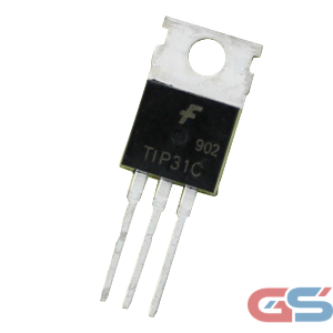
TIP31C TO-220 NPN Transistor
Original price was: ₹18.00.₹16.00Current price is: ₹16.00.
Description
TIP31C TO-220 NPN transistor delivers reliable medium-power switching and amplification in a compact, industry-standard package trusted by engineers and hobbyists alike. With a continuous collector current rating of 3A and a collector-emitter breakdown voltage of 100V, this transistor handles a wide range of DC motor drives, relay drivers, lamp controls, and audio amplifier stages with ease. The robust TO-220 package provides excellent thermal dissipation, especially when paired with a suitable heat sink, making it a dependable workhorse for both prototype and production designs.
Key Features
- NPN silicon transistor in industry-standard TO-220 package for easy through-hole mounting
- 100V collector-emitter breakdown voltage (VCEO) — suitable for higher-voltage switching applications
- 3A continuous collector current (IC) — handles medium-power loads without additional components
- 40W power dissipation with heat sink — significantly higher than small-signal transistors
- DC current gain (hFE) of 10–50 across a wide collector current range for predictable operation
- Complementary pair with TIP32C (PNP) — ideal for push-pull and H-bridge circuit designs
- RoHS-compliant construction — meets modern environmental standards
- Mounting tab at ground potential (collector) — allows direct heatsinking without insulating pads in many circuits
Specifications
| Parameter | Value |
|---|---|
| Transistor Type | NPN Silicon |
| Package | TO-220 |
| Collector-Emitter Voltage (VCEO) | 100V |
| Collector-Base Voltage (VCBO) | 100V |
| Emitter-Base Voltage (VEBO) | 5V |
| Continuous Collector Current (IC) | 3A |
| Peak Collector Current (ICM) | 5A |
| Base Current (IB) | 1A |
| DC Current Gain (hFE) | 10–50 (@ IC = 1A) |
| Collector-Emitter Saturation Voltage (VCE sat) | ≤ 1.2V (@ IC = 3A, IB = 0.3A) |
| Power Dissipation (PD) — with heat sink | 40W |
| Power Dissipation (PD) — free air | 2W |
| Transition Frequency (fT) | 3 MHz (typ.) |
| Operating Junction Temperature (TJ) | –65°C to +150°C |
| Storage Temperature (Tstg) | –65°C to +150°C |
| Thermal Resistance (junction to case) θJC | 3.125°C/W |
| Pin Configuration (front view) | Base | Collector | Emitter |
| Complementary PNP Type | TIP32C |
| Compliance | RoHS |
Compatible Applications
- DC motor speed control circuits (PWM-driven)
- Relay driver stages (12V and 24V coils)
- Solenoid and valve drivers
- Lamp and LED driver circuits (up to 3A loads)
- Audio power amplifier output stages
- Push-pull and H-bridge configurations (with TIP32C)
- Linear voltage regulator pass elements
- Switch-mode power supply (SMPS) circuits
- Arduino, Raspberry Pi, and microcontroller load switching
- Industrial control and automation circuits
Installation Guide
General Through-Hole PCB Installation
- Identify the three pins from the front (label side): Base (B), Collector (C), Emitter (E) — left to right.
- Insert the transistor into the corresponding PCB footprint, ensuring correct pin orientation.
- If required, bend the leads at 90° for horizontal (lying flat) mounting.
- Solder each pin and trim excess lead length.
- If power dissipation exceeds 2W, attach a TO-220 compatible heat sink to the metal tab before powering the circuit.
DC Motor Driver (Microcontroller)
- Connect the Base pin through a 1kΩ–10kΩ resistor to the microcontroller GPIO output pin.
- Connect the Collector to the negative terminal of the motor (motor’s other terminal goes to the supply rail).
- Connect the Emitter to GND.
- Place a flyback diode (e.g., 1N4007) across the motor terminals (cathode to supply, anode to collector) to suppress inductive voltage spikes.
- Apply PWM signal to the base resistor to control motor speed.
Relay Driver
- Connect the Base through a current-limiting resistor (typically 1kΩ) to the control signal.
- Connect the Collector to one terminal of the relay coil.
- Connect the other terminal of the relay coil to the supply voltage (VCC).
- Connect the Emitter to GND.
- Add a flyback diode in parallel with the relay coil to protect against back-EMF.
Heat Sink Mounting
- Apply a thin, even layer of thermal paste to the metal tab of the TIP31C.
- Align the tab with the heat sink mounting hole.
- If the circuit requires the collector to be electrically isolated from the heat sink, insert a TO-220 insulating mica or silicone pad between the tab and heat sink.
- Secure with an M3 screw and nut — do not overtighten.
- Verify electrical isolation with a multimeter if an insulating pad was used.
Whether you are building a motor controller, relay driver, or audio amplifier, the TIP31C TO-220 NPN transistor gives you the headroom, reliability, and thermal performance to do it right. Add it to your order today and keep your projects moving forward.
| Weight | 1.2 g |
|---|
Sorry, no reviews match your current selections